PLC Basic Structure and I/O devices
PLC or programmable logic controllers are widely used in industries to control processes because they eliminate the need for complex rewiring and investment in additional hardwares such as timers, counters and relays. PLCs have terminals to connect analog and digital input and output devices. Various timers, counters, logic operations, latches, memory and many other function are in-built inside PLC.
The PLC model that will be described here will be LOGO! PLC ( relay type) with 8 inputs and 4 outputs. The following topics shall be covered.
a. Wiring of input and output devices
b. Writing ON-requirements and Logic expression
c. Latching and interlock
d. Timers and Counters
When you first start to learn about programming a PLC, the difficult part is usually how to place the correct type of contacts in the program to perform the intended task. One also find it confusing to relate the internal contacts and the external devices, for example the program may use a normally close contact but the external device is a normally open type.
There are systematic steps to follow to form a logical expressions or Boolean expressions that governs the behaviour of output devices with the states of the input devices. Once these expressions have been made, creating the PLC program is rather easy.
The picture shows a LOGO! power unit and a LOGO! PLC unit. The PLC unit has 8 input ports and 4 output ports.The LOGO! power converts AC 110 - 240V to 24V DC.
What are the various input and output devices and how do we connect them?
Input devices can be of discrete or analog type. Discrete type produces only two different logic states or voltage levels. One is 0 which is the same as 0V and the other is 1 which equals the supply voltage it is connected to, 24V in our case. Push buttons, float switch, switch and some proximity sensors fall under this category. Analog sensors produce various voltage/current values corresponding to the measured value.
I/O Connection
Input devices can be categorized as two wire and three wire type. In a two wire device, one terminal is connected to the input port of the PLC while the other terminal is wired to the +supply, 24V. In the three wire device, it is almost the same as two wire except that there is an additional wire that should be connected to the GND (0V or M).
Three wire device has standard color for the wires. The red or brown for +supply, blue for 0V and black for the signal which goes to the PLC input port.
The exact connection of devices to PLC is shown in the schematic diagram. This schematic diagram is build using EasyEDA. It is a fantastic browser based application and a complete EDA tool. You can sign up for free and start enjoy using it.
The schematic diagram shows that LOGO! power unit that produces 24V and it is connected to L+ of the PLC unit. The negative terminal from LOGO power is connected to M of PLC unit ( M is the Ground). S1 is a three wire device and BK ( normally black in color) is the signal wire which ends up in the PLC input port while BR ( brown or red) is the power and BL ( blue) is the ground respectively. All the two wire devices have one side connected to 24V line and the other to the input port of PLC. On output side of the PLC, all the terminals labelled 1 are connected to 24V while the terminals labelled 2 are connected to one side of the load and the other side of load will be connected to f M. The terminals labelled 1 and 2 at the output Q acts as contacts /switches which are controlled by the PLC program. When the switches close, a complete circuit with load is formed.
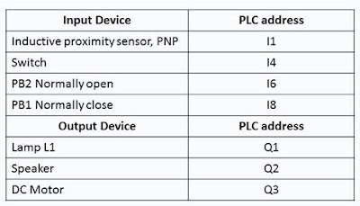
The I/O table is the summary of all the hardware ( input devices and output devices) that are connected to the PLC and used in the task. It serves as a quick reference during programming.


No comments:
Post a Comment