
A. Diode operation
1. Forward Bias Mode ( FB )
For diode to be in a forward bias mode (conduction mode), the anode must be connected towards the positive side of the voltage source and the cathode towards the negative side of the source. In this mode, the diode behaves similar to a closed switch. The resistance inside diode is very low (a few ohms).
There can be other components between the diode and voltage source such as resistors but it can be still be in FB mode as long the anode is directed towards the positive side of voltage source.
There can be other components between the diode and voltage source such as resistors but it can be still be in FB mode as long the anode is directed towards the positive side of voltage source.
In the following diagram, the lamp has a resistance of 5Ω and diode threshold voltage is 0.7V.

The voltmeter shows a drop of about 0.7V across the diode and 4.3V across the lamp. Use Ohm's law to calculate the current value in the circuit.
2. Reverse Bias mode (RB)
When the anode is connected towards the negative of the power supply and the cathode towards the positive side, then the diode will be in the reverse bias mode (cut-off mode). Current cannot pass through the diode because of the high resistance value (in megaohm range) inside the diode. It is similar to a switch that is in an open state. Due to the high resistance of diode, almost all of the voltage from the supply will fall/drop across the diode and none across the load/lamp. The current value is almost zero.

The meter reading shows almost 5V across the diode and 0.00002V across lamp. Don't forget the multiplier x10^-3 on the right multimeter.
B. Diode Testing
How to test diodes - there are two ways:
a. Use diode test mode which provides voltage reading
b. Use resistance measurement mode
1. Diode test mode
Digital multimeters can test diodes using the diode test mode. A good diode gives a reading between 0.5V to 0.8V in the forward bias mode for silicon diode. A good Germanium diode gives reading between 0.2V to 0.3V.
In reverse bias, both silicon and germanium will show OL ( open load).

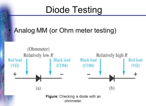
2. Resistance measurement
Analog meters such as ohmmeter does not have a diode test mode. In this case, we can use resistance measurement to check if the diode is in good condition or not. A good diode shows a reading of less than 100 ohm in forward bias whereas in reverse bias mode it shows more than 1000 MΩ.

C. Diode applications
1. Rectification - conversion of AC signal to DC signal
1.1 Half wave rectifier
Constructed using a single diode and a load.
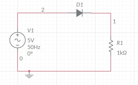
The waveform before the diode and after the diode were plotted using an oscilloscope. It can be seen that the negative cycle of the input wave has been cut off by the diode because during this part of the cycle, the diode is in the reverse bias mode or in the off state. No conduction of current takes place during this time. Also notice that the the final peak voltage is always about 0.6 -0.8V less than the input peak voltage. Why is that? ( Still remember the threshold voltage that diode requires for it to enter the conduction mode!)


The output from a half wave rectifier is a DC but even though current flows in one direction it still not a steady DC. The DC value fluctuates in the positive direction. Hence it is still not suitable to be used to drive most loads.The average output voltage of the rectified wave can be calculated using the formula:
Example:
Answer the following questions based on figure below.
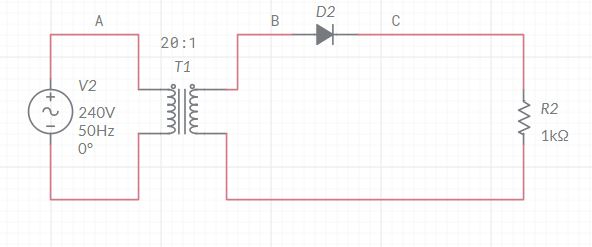
a. Is the transformer a step up or step down type?
b. State the peak voltage value at the primary and secondary side.
c. Type of signal ( AC/DC) at point A, B and C
d. The difference in peak value between point B and C.
e. The average value at output.
f. Plot the graph of the waveform at point B and C.
Answers
a. Step-down
b. 240V , 12V
c. AC, AC, DC ( fluctuating DC)
d. About 0.7V
e. 3.72 V

Half wave rectifier with smoother circuit
The diagrams below show the output for different values of capacitors.
C = 10uF

C=100uF

C = 300uF

C = 1000uF
The figure below shows the area/region of the waveform where the capacitor gets charged up and where it discharges itself.


Vave = Vp/π Vp =Peak output voltage
Example:
Answer the following questions based on figure below.

b. State the peak voltage value at the primary and secondary side.
c. Type of signal ( AC/DC) at point A, B and C
d. The difference in peak value between point B and C.
e. The average value at output.
f. Plot the graph of the waveform at point B and C.
Answers
a. Step-down
b. 240V , 12V
c. AC, AC, DC ( fluctuating DC)
d. About 0.7V
e. 3.72 V
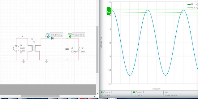
Half wave rectifier with smoother circuit
As we have seen previously that the fluctuating DC is still not suitable for driving loads. Hence we have to somehow make it a steady DC voltage. This can be done by fixing a capacitor parallel to the load. Capacitors stores charge or electricity. When the input voltage reaches the peak, the capacitor will be also be fully charged and keeps this charge. As the input voltage decreases from the peak value and become less than the capacitor, it is time for capacitor to release its charge into the load. Capacitor acts as a backup to provide energy to the load.
The diagrams below show the output for different values of capacitors.
C = 10uF

C=100uF

C = 300uF

C = 1000uF

The figure below shows the area/region of the waveform where the capacitor gets charged up and where it discharges itself.

What is Ripple voltage?
The fluctuation of the dc value from the maximum to its minimum is called ripple as shown in diagram below.

Capacitor is used to remove the ripples!!
1.2 Full Wave Rectifier
A Full Wave Rectifier is a circuit, which converts an ac voltage into a pulsating dc voltage using both half cycles of the applied ac voltage. It uses 4 rectifier diodes forming a shape to looks like a bridge, hence the name bridge rectifier. A real life bridge rectifier looks like picture below.
It is connected to an AC supply and load as figure below.

Operation of full wave rectifier ( without smoothing)

Positive half cycle
Negative half cycle
Full wave rectifier output waveform

Average output voltage of full wave rectifier ( before smoothing effect) is given by the formula below.
Vave = 2Vp/π
Comparison between full wave and half wave rectification waveforms

Removing ripple in full wave bridge rectifier
Again, capacitors are used to remove ripple

2. Voltage Regulation using Diode and Zener Diode
The function of a regulator is to provide a constant output voltage to a load connected in parallel with it in spite of the ripples in the supply voltage. The best way will be by using zener diode. However diodes can also be used. Let's see how diode works as voltage regulators.
Using diode to regulate voltage across load
Three silicon rectifier diodes in series are placed parallel to the load. Each diode needs 0.7V to turn on. In total 2.1V is all the is needed for current to flow through this path. The voltage across the load will also be fixed to this potential difference. Even if the rectifier output increases, the voltage across the load maintains at 2.1V.

How many rectifier diodes are needed if the load voltage is to be regulated to 7V?
Using Zener diode to regulate voltage
Lets look at symbol and behaviour of zener diode. Zener diode are specially made diodes which are intended to work in the reverse bias mode and not in the forward bias mode. Hence when we connect a zener parallel to the load, the cathode must always be connected to the positive side of the voltage source.

Zener diode comes in different Vz values. We need to use one that suits the circuit intended.
An example using Multisim Live circuit simulator is shown below.

Multisim Live is a free, online circuit simulator that includes SPICE software, which lets you create, learn and share circuits and electronics online.
No comments:
Post a Comment